Wednesday 19 September 2012

Use a lathe to make a punch

Work in date: 19/09/2012
List of tools and Equipment used:
Lathe, Overalls and safety boots, Glasses,

Process:
Turn power on, adjust lathe all equipment to correct position.
Put "round" on the lathe and make tight.
Adjust lathe scales to "0", and cutting to 90°, make tight.
Calculate the "round" cutting length and diameter.
Length: 18mm, 22mm, 25mm, 28mm, 32mm, 75mm and 12mm
Diameter leave: 12.57mm, 15.75mm, 18.9mm, 22.1mm, 24.02mm, 24.8mm and 22.23mm
Diameter cutting:
25-12.57=12.43mm
25-15.75=9.25mm
25-18.9=6.1mm
25-22.1=2.9mm
25-24.02=0.98mm
25-24.8=0.2mm
25-22.23=2.77mm
Last cutting from 12mm length to leave 2mm × 45°

Reminder:
After finish each one stage, must adjust scales to "0"

Tuesday 11 September 2012

Welding

Work in date: 23/08/2012

Oxy-acetylene welding is one type of welding process used in metal fabrication. This type of welding uses a torch fed by an oxygen and acetylene fuel mixture to heat the metal parts to be welded as well as the welding filler rod used to add material to the weld. Oxy-acetylene welding has been in use since the turn of the 20th century, and does not require electrical power, allowing the welding equipment to be used in a wide variety of environments.


Fusion Welding(Oxyacetylene)Processes:


Correct turn valve on, and check pressure of gas. Use weld lighter spark carefully fire gas, adjust fire to neutral flame. Find two same size steels plates, and use weld magnet hold one of them. One hand hold the weld torch, other hand hold weld filler rod. Put two steels plates connect a sideways. Movement of rod straight, and motion of blowpipe sideways. After finished, turn off all valve, and put all equipment back.

Work in date: 04/09/2012
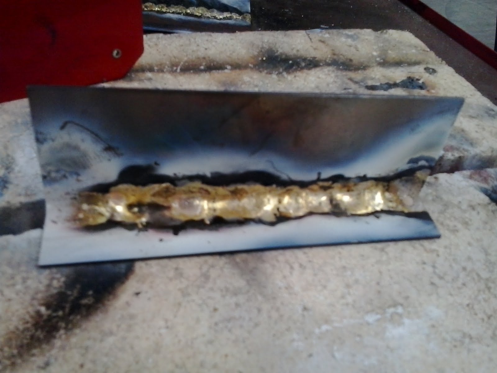
Brazing Processes:

Bronze welding flux for braze welding of cast iron, steel, steel castings, malleable iron, etc. 


  • Correct turn valve on, and check pressure of gas. 
  • Use weld lighter spark carefully fire gas, adjust fire to  oxidizing flame.
  • Find two same size steels plates, and use weld magnet hold one of them and leave a gap between steels.
  • One hand hold the weld torch, other hand hold weld filler metal and with bronze weld flux.
  • Put two steels plates connect a sideways.
  • Movement of weld filler metal straight, and motion of blowpipe sideways.
  • After finished, turn off all valve, and put all equipment back.
Potential hazards and injuries:

Metal splinter, Hands and eye injuries, Dust particles, Hot Metal, Sparks, Sharp edges and burrs, Explode.

List some photos from workshop:


Work in date: 18/09/2012

MIG Welding

Metal Inert Gas (MIG) welding, also sometimes called Gas Metal Arc Welding (GMAW) is a process that was developed in the 1940s for welding aluminum and other non-ferrous metals. MIG welding is an automatic or semi-automatic process in which a wire connected to a source of direct current acts as an electrode to join two pieces of metal as it is continuously passed through a welding gun. A flow of an inert gas, originally argon, is also passed through the welding gun at the same time as the wire electrode. This inert gas acts as a shield, keeping airborne contaminants away from the weld zone.

Process:

The Welder: Inside the welder you will find a spool of MIG wire and a series of rollers that pushes the wire out to the welding torch. There isn't much going on inside this part of the welder, so it's worth it to take just a minute and familiarize yourself with the different parts.

The Gas Supply: Assuming you are using a shielding gas with your MIG welder there will be a cylinder of gas behind the MIG. This is either 100% Argon or a mixture of CO2 and Argon. This gas shields the weld as it forms. Without the gas your welds will look brown, splattered and just generally not very nice.

The Welding Torch: The welding torch is the business end of things. It's where most of your attention will be directed during the welding process. The MIG torch consists of a trigger that controls the wire feed and the flow of electricity.
Clamp the negative lead from the welder onto your project or, in this case, the welding table 
Butt joint
Lap joint
T-joint
Edge joint

Electrical Engineering

Sunday 9 September 2012

Drill Gauge

Work in date: 21/08/2012                                                                                                                      
List tools used and describe:
Center Punch: It is a hand tool used to produce a dimple in a workpiece (for example, a piece of metal).
Vice: A tail vice is mostly used in design technology, it holds your work-piece firmly.
Bastard File: A bastard file or a mill bastard file is a file whose teeth configuration is in between a rough or coarse file and a 'second cut' file.

Second Cut File: A second cut file is a grade or pitch finer than a bastard file and is used for cutting hard metals.
Pillar Drill: A pillar drill is a stationary style of drilling machine that can be mounted on a stand or bolted to the floor or workbench.


Scriber: A scriber is a hand tool used in metalworking to mark lines on workpieces, prior to machining. 
Engineer Protractor: Engineer's protractor is a general purpose tool used for the measuring / checking of angles.
Steel Rule: A ruler, sometimes called a rule or line gauge, is an instrument used in geometry, technical drawing, printing and engineering
Ball Pein Hammer: The type most commonly used is the ball pein hammer, which has a flat striking face and a ball-shaped end (call the pein). Hammer heads are made from medium carbon steel. The two ends must be hardened and tempered, the centre of the head with the eye being left soft. It is specified according to its weight.
Engineers try-square: It is composed of two parts, the stock and the blade. They are usually made from bright mild steel with the blade being hardened and tempered so that it resists damage.
Engineer's blue: It is a highly pigmented paste used to assist in the mating of two or more components.
Jenny Caliper: A jenny caliper, which features a pair of arms connected by a circular hinge at one end.
Hacksaw: It is a fine-tooth saw with a blade held under tension in a frame, used for cutting materials such as metal or plastics.
Abrasive paper: It is used to remove small surfaces from materials.


Describe the process used in completing the task:
  • Select a steel metal as exercise target, then clean this material and check size;
  • One side use engineers blue ink to brush for marking;
  • Square bottom and top edge using engineers protractor;
  • Stamp bench number on back face;
  • Mark out holes, lightly center punch using scriber;
  • There are five holes on the metal, and each one has different size: 4, 6, 8, 10, and 12mm, 
  • Check top and bottom size length if correct.
Work in date: 22/08/2012  

Describe the process used in completing the task:
  • Using hacksaw cut unnecessary parts, then use rough and smooth files to polish the corners of the steels.
  • File to shape ensuring: Point X is sharp not rounded, point Y is clear not undercut, 24mm width is parallel with max variation of ±0.05mm,
  • Keep top corner is 45 degree.
  • Number stamp hole 4, 6, 8, 10, and 12mm.
  • Using pillar drill to drill six different size holes.
  • Using abrasive paper polish the steel.
Potential hazards and injuries:
Metal splinter, Dust particles,Hot Metal, Sparks, Noise, Sharp edges and burrs, Hands and eye injuries

List some photos from workshop:

Sunday 2 September 2012

Workshop Tools

1. What is the name of the hammer most commonly used in Automotive engineering?

The most common hammer in an automotive workshop is the ball pein or engineer's hammer. The soft-face & deadblow hammers are also used.

2. What would you typically use one for?

The ball pein hammer is also used for hitting chisels and punches, but sometimes you need just to tap a component, to position it. A steel hammer might mark or damage it, especially if it's made of a softer metal like aluminum. In such cases a soft-face hammer should normally be used for the job. Some are very soft with rubber or plastic heads through to those using brass or copper. 

3. Why would you use a soft faced hammer?

Soft material made to protect surface of components or parts by damaged hit. 

4. What type of hammer would you use to give a really strong blow to a chisel?

When a large chisel needs a really strong blow, it's time to use the lump hammer.

5. What would you use a mallet for in Automotive Engineering?

It's a special purpose tool, and is often used for moving things into place where it is important not to damage the item being moved.

6. When would you use a dead blow hammer?

In auto repair they are commonly used for chassis work, dislodging stuck parts and sometimes used for hubcap installation and removal (e.g. knock-off hubs). They can be used to pop out small dents as well.

7. What can cause a hacksaw blade to clog?

The hacksaw is not be of right pitch, or number of teeth in an inch of blade. If a blade cutting through a thick section of metal has too many teeth, in other words the pitch is too fine, they can clog up and stop cutting.

8. What can happen if the blade is too coarse for the job it is intended for?

If the blade is too coarse the saw teeth could be stripped off of the blade at it try's to cut.

9. What should you do before and after using a hacksaw?

Before using a hacksaw should be determine the correct blade (and number of teeth) by laying the blade across the section being cut. Normally, at least 3 teeth should touch the metal at that point. This will ensure that the blade can do its job. After the job is done, the tension on the blade should be loosened, to prevent the frame from distorting over time.